
The red lines at drawn the bottom show you how the copper tracks are aligned on the other side of the board. The next photo shows the front of the completed & soldered circuit. Step 5: Charging Your Battery – Part 1B circuit diagram of solar panel battery charger step 5 The main purpose of the diode is to avoid current dissipation from the battery to the solar cell when this low voltage situation occurs in the solar cell. If the voltage of the solar cell drops below 1.4 volts & with the 0.2V the blocking diode takes there won’t be enough potential to charge the 1.2V battery. The solar cells’ +ve terminal is interfaced through the diode to the +ve terminal of the 1.2V battery. Step 4: Charging Your Battery – Part 1A circuit diagram of solar panel battery charger step 4Īnd now we come to making your own battery charger. Try the experiment by attempting to enlighten the LED with the battery alone, or with the solar panel only. You can even power the solar panel from a powerful torch or lamp by shining it onto the panel. If the battery is fully charged & you have a sunny day the LED should light up. Then connect the -ve wire of the solar panel to the other LED leg. The longer leg of an LED is always interfaced with the +ve side of the circuit. Use some more wire supplied to connect the +ve end of the battery holder to any longer of the two legs of the LED.
ICIRCUIT SOLAR PANEL PLUS
We can try to use the battery’s voltage plus the voltage of solar panel to operate the LED.Ĭonnect the NEGATIVE leg of the battery holder to RED POSITIVE terminal of the solar panel. The 2-3V solar panel ‘ll also carry a lot of problems while lighting the LED by itself.

The 1.2V battery on its own ‘ll not be strong enough to enlighten the LED. Place a rechargeable fully charged 1.2V Nimh battery into battery holder-I assume you know the right way round to insert it. Step 3: Main Experiment circuit diagram of solar panel battery charger step 3
ICIRCUIT SOLAR PANEL FREE
Always make sure that contact points are free from grease & clean. Not the most fantastic job in the world but it is held securely. Allow some tape to move round the solar side to ensure a firm placement.Īlso shown is the soldered method. I don’t suggest using glue! – you won’t get the wire staying in touch with the contacts because the glue gets in the way. The wire ends were stripped, flattened onto the contacts & firmly taped in place. Yes that is cellotape! The red squares show where the contacts are.

You can find an example of the solder-less method…. This ‘ll keep the wire in its place & block strain on the contacts, plus wires. Soldered is the pretty best method to go with & I ‘ll show you snapshots of both – if you like using more panels or using the single panel a lot you ‘ll find it best to mount the panel onto a piece of sheet wood or plastic. Step 2: The Solar Panel – attaching wiresĬircuit diagram of solar panel battery charger step 2Īttaching the black & red wires to solar panelįor attaching the wire, one can make use of the soldered or the un-soldered method. Read> Components connectivity & polarity
ICIRCUIT SOLAR PANEL HOW TO
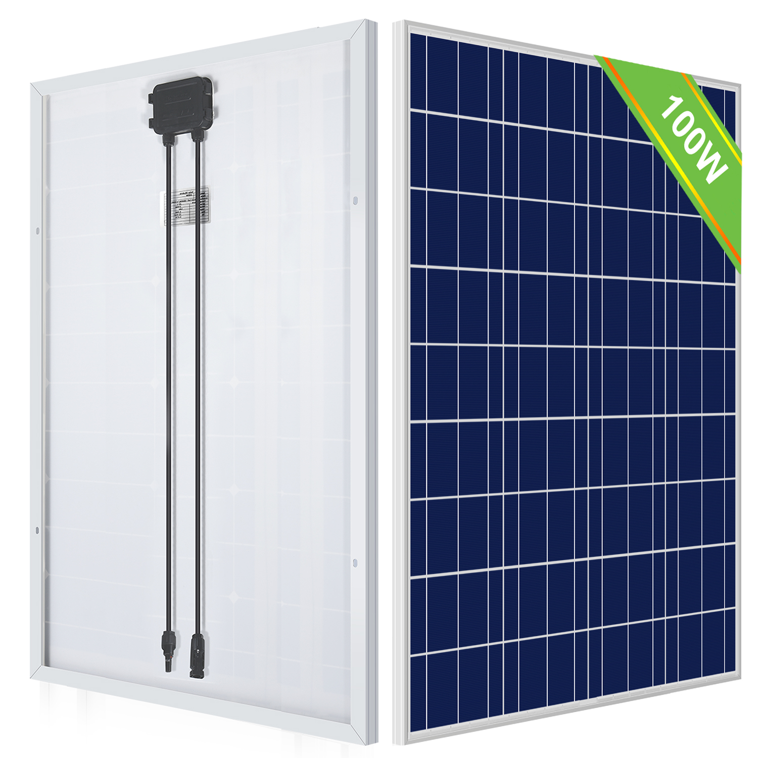
HINT – you should possibly purchase a multi-meter & know how to use it-this ‘ll tell you important information about typical voltages & currents your solar panel ‘ll produce in variable weather situations. This solar panel ‘ll give an output of max of 3V at 150ma. I have marked the +ve side by adding black small dots on that side. On the solar panel in center of left-side & right-side you ‘ll see a very small panel of smooth meta-this is the -ve/+ve terminals. Solar Panel – The back of the solar panel is shown in image. Wires -Usually included at least 4 wires-a black & red wire for the solar panel, a brown wire used as a jumper & another wire for use in un-soldered testing. This must be very close to the -ve/ground. The diode constitutes a circular band across its barrel at one end of the diode. This blocking diode also requires to be placed in the circuit in a correct orientation. The longer leg should receive current from the +ve terminal/direction.ġN5817 DIODE – this diode lets the current flow in only one direction-this blocks battery’s power, discharging through the solar panel at night. A LED must be kept in the circuit the correct way around. 3.2-3.6V forward voltage, with 10000 mcd at 20 ma. LED – this is the high-intensity light emitting diode. & comes into play with two pins, one for the +ve & one for the -ve ends, they’ll be soldered into the strip-board.ġ00 Ohm resistor – at a point this was necessary in the kit as the LED couldn’t cope with some of voltages in the experiments-however, the new LEDs do this & the resistor is simply in there because it is advertised as such! Maybe you ‘ll be needing it when you ‘ll expand your system. The Battery Holder … holds your batteries….


 0 kommentar(er)
